Firmware OTA and Bootloader Design Notes
Direct answer. A firmware update path is designed together with the bootloader, before the first unit ships. Decide the flash layout, how images are signed and checked, how a failed update rolls back, and what happens if power drops halfway. Test each failure case on real hardware. Changing these decisions after units are in the field is expensive.
1.0 Why the update path is a design decision
An update mechanism looks like a feature you can add later. In practice it sets constraints on almost everything else: how much flash the application may use, how the memory map is laid out, which keys exist and where they are stored, and how the production line programs the first image. Once units ship, the bootloader is the one piece of code you cannot safely replace, so anything it lacks on day one (signature checks, a second key slot, a resumable swap) stays missing for the life of the product.
So we treat the update path as part of the architecture, written down in the same document as the memory map and the communication protocol, and reviewed before application work gets far.
2.0 Questions to answer first
| Question | Why it matters | Typical options |
|---|---|---|
| How does a new image reach the device? | Sets transport, chunking and resume logic | BLE, USB, UART, Wi-Fi/cellular, SD card, debugger only |
| Where is the new image stored while it downloads? | Determines flash budget | Second internal slot, external flash, RAM (small images only) |
| How is the image authenticated? | Prevents running code you did not build | Signature over image and header; hash-only is integrity, not authenticity |
| Can an older image be installed again? | Downgrade attacks and support policy | Monotonic version counter, allow-list, or explicit downgrade flag |
| What happens if the new image fails? | Field units that stop working | Test-boot then confirm, watchdog-driven revert |
| Who holds the signing key? | Release process and access control | HSM or offline machine; never the build server’s working copy |
| What does the factory flash? | Line programming and first boot | Bootloader + signed application + provisioning data |
If the answers are not known yet, record them as open decisions with an owner. Do not ship a bootloader written to “accept anything for now”; it cannot be tightened in the field.
3.0 A dual-slot layout that tolerates power loss
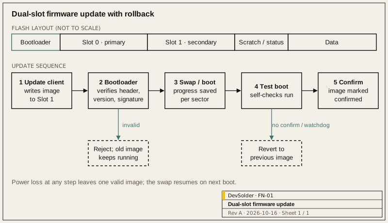
If the application fits in less than half of internal flash after reserving the bootloader, use two slots plus a scratch area. The bootloader never runs code from a slot it has not verified.
3.1 Flash layout
| Region | Contents | Written by |
|---|---|---|
| Bootloader | Immutable first-stage code, public verification key | Factory only |
| Slot 0 (primary) | The image that runs | Bootloader during swap, or factory |
| Slot 1 (secondary) | The downloaded candidate image | Application’s update client |
| Scratch / swap status | Progress markers so a swap can resume after reset | Bootloader |
| Settings / data | Calibration, pairing keys, user data | Application; must survive updates |
Keep the data region outside both slots and give it a versioned format. An update that changes the data layout needs a migration step, and the old image must still be able to read the data if it is rolled back.
3.2 Update sequence
- The update client receives the image in chunks and writes it to slot 1. It verifies length and hash before marking the slot as pending.
- On the next reset, the bootloader checks the image header, version and signature in slot 1.
- If valid, the bootloader swaps slots (or, on parts that support it, boots slot 1 directly), recording progress in the scratch area after each sector so an interrupted swap continues on the next boot.
- The new image runs in a test state. It runs its self-checks: peripherals initialise, the communication link comes up, the data region can be read.
- If the checks pass, the application marks the image as confirmed. If it resets before confirming, or the watchdog fires, the bootloader reverts to the previous image.
This is the model used by open-source bootloaders such as MCUboot, and its design documentation is a good reference for the swap and revert details. We do not require a specific bootloader; on some parts a vendor bootloader or a small custom one is the better fit. The sequence above is what we check for regardless of the implementation.
3.3 Single-slot and external-flash variants
When internal flash is too small for two slots, the candidate image can go to external flash. The bootloader then copies it in. This works, but the copy step must be resumable, and the external flash contents must be verified again before copying, because the external chip is easier to tamper with. A single-slot design with no fallback image should only be accepted when the device can always be recovered over a wired interface, and that recovery procedure is documented.
4.0 Signing and keys
Integrity checks (CRC, SHA-256) catch corruption. They do not tell you who built the image. For that you need a signature over the image and its header, verified with a public key that the bootloader holds in a region the application cannot overwrite.
Practical points we write into the design:
- The private signing key lives outside the normal build environment. Release builds are signed in a separate, logged step.
- Plan for key rotation. Either the bootloader holds more than one public key, or there is a documented procedure to update the trusted key with a signed image.
- Separate development and production keys. Development boards should not accept production-signed images by accident, and production units should never accept development-signed ones.
- Version numbers in the signed header, not only in the application, so the bootloader can enforce an anti-rollback policy.
NIST SP 800-193 describes platform firmware resiliency in terms of protection, detection and recovery, and it is a useful checklist even for small devices. The IETF’s RFC 9019 describes a firmware update architecture for IoT devices and the roles involved.
5.0 Transport and resume
Whatever the transport, the update protocol needs the same properties:
- Chunked transfer with an offset, so a dropped link resumes instead of restarting.
- A hash of the full image sent up front, checked after the last chunk.
- An explicit “image complete” step, separate from “reboot now”, so the host can decide when to restart.
- Clear error codes for the host: wrong image type, version rejected, not enough space, verification failed.
On BLE, throughput depends on connection parameters and MTU negotiated with the phone, and both vary by phone model. Design for the worst case you can test, and show progress to the user. For device protocol design in general, see the companion note on BLE and USB device communication.
6.0 Test cases we run before shipping
| Case | Expected result |
|---|---|
| Power removed during download | Old image still runs; download resumes or restarts cleanly |
| Power removed during swap (several points) | Swap resumes on next boot; device ends in one valid image |
| Corrupted image (one byte changed) | Rejected before swap; error reported to host |
| Image signed with wrong key | Rejected |
| Older version image | Rejected, or accepted only under the documented downgrade rule |
| New image that never confirms | Reverted after reset or watchdog |
| New image with changed data format | Data migrated; rollback still reads data |
| Factory-programmed unit, first update | Works with the line’s image and provisioning |
The power-loss tests need a controllable supply or a relay on the power line, and a script that cuts power at each phase boundary of download and swap, repeats each point in a loop, and logs which image booted after every cycle. The cut points and cycle count go into the test record with the results.
7.0 What goes into the handover
- Flash layout table and the reasoning behind slot sizes.
- Image header format, signing procedure and key custody notes.
- The update protocol description with message formats and error codes.
- The test list above with the results from the hardware it ran on.
- Factory programming steps for the bootloader and the first image.
If you are planning firmware for a new device or need an update path added to an existing one, the Embedded Firmware page describes how we work, and the Web, Cloud and Device Management page covers the server side of update distribution. You can describe your project on the Discuss a Project form.
References
- MCUboot design documentation: https://docs.mcuboot.com/design.html
- NIST SP 800-193, Platform Firmware Resiliency Guidelines: https://csrc.nist.gov/pubs/sp/800/193/final
- IETF RFC 9019, A Firmware Update Architecture for Internet of Things: https://datatracker.ietf.org/doc/html/rfc9019
Frequently asked questions
Can we add OTA updates to a product that has already shipped?
It depends on the bootloader already on those units. If it can accept a new application image over some interface, you can usually add an update client to the application and ship it through that path. If it cannot, units in the field can only be updated over a wired connection, and the improved design applies to new production.
Do we need two full application slots?
Two slots give the simplest recovery story, but they halve the space available to the application. External flash for the candidate image, or a compressed image, are common alternatives. The choice should be made from a flash budget written down early, not discovered when the application outgrows its slot.
Is a CRC check enough to protect the update?
A CRC or hash detects corruption in transit. It does not prove the image came from you, so anyone who can reach the update interface could install their own code. A signature checked by the bootloader closes that gap, and the key handling around it matters as much as the algorithm.
How do you test power loss during an update?
We script it: a controllable supply or relay cuts power at each phase boundary of the download and the swap and at offsets inside each phase, repeats every point in a loop, and logs which image booted after each cycle. Results go into the handover so the next engineer can rerun them.
Which bootloader do you recommend?
The one that fits the part, the flash budget and your security needs. MCUboot is a well-documented open-source option on many microcontrollers; vendor bootloaders are sometimes the better fit. We compare them against the questions in section 2.0 and write down why one was chosen.