EMC Pre-Compliance Testing Before the Lab: A Bench Plan
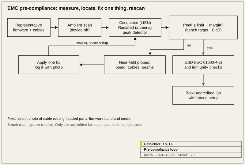
Direct answer. EMC pre-compliance is a set of bench measurements that predicts how a prototype will do at the accredited lab: conducted emissions through a LISN, radiated scans with an antenna and spectrum analyser, near-field probing to find sources, then ESD on every touchable surface. Book the lab once your own scans show about 6 dB of margin.
1.0 What pre-compliance is for
A full lab day for a small product is expensive, and a failed session usually means a board spin plus another booking. Pre-compliance exists to make the first lab visit a confirmation. It does not prove compliance. The bench has no calibrated site, ambient signals from FM radio and Wi-Fi sit on top of your trace, and the antenna factor and cable loss are only as good as the numbers you entered.
Where it earns its keep: ranking emissions, showing whether a fix moved a peak by 2 dB or 12 dB, and finding the obvious failures (a switching regulator harmonic, an unterminated clock line, a long USB cable radiating) weeks before the lab would.
2.0 Know the limit lines you are aiming at
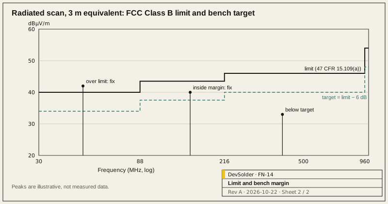
Pick the standard first. For a digital product sold in the US, 47 CFR Part 15 sets the unintentional radiator limits. Converted to dBµV/m, the Class B radiated limits at 3 m are:
| Frequency (MHz) | Limit (µV/m at 3 m) | Limit (dBµV/m) |
|---|---|---|
| 30–88 | 100 | 40.0 |
| 88–216 | 150 | 43.5 |
| 216–960 | 200 | 46.0 |
| above 960 | 500 | 54.0 |
Source: 47 CFR 15.109(a). The tighter limit applies at band edges.
Class B conducted limits on the AC line, measured with a 50 µH / 50 Ω LISN from 150 kHz to 30 MHz (47 CFR 15.107(a)):
| Frequency (MHz) | Quasi-peak (dBµV) | Average (dBµV) |
|---|---|---|
| 0.15–0.5 | 66 falling to 56 | 56 falling to 46 |
| 0.5–5 | 56 | 46 |
| 5–30 | 60 | 50 |
The lower limit applies at band edges.
Part 15.109(g) also allows CISPR 22 radiated limits as an alternative (FCC limits still apply above 1 GHz), and products for the EU are assessed against harmonised standards such as EN 55032. Get the exact edition and class from your test lab before you set up the limit lines in the analyser, because a Class A line drawn by mistake hides 10 dB or more of problems.
3.0 The bench setup
A useful setup does not need a chamber:
- Spectrum analyser with a peak detector, ideally with EMI bandwidths (9 kHz below 30 MHz, 120 kHz from 30 MHz to 1 GHz, 1 MHz above) and a quasi-peak or average detector for the final check.
- LISN for conducted emissions, 50 µH / 50 Ω, with a transient limiter in front of the analyser input. Connect the limiter before you power the device. Switch-on spikes can damage an unprotected front end.
- Antenna covering 30 MHz to 1 GHz (a biconical/log-periodic pair or a small hybrid) on a tripod at a fixed distance, often 1 m on a bench. Readings at 1 m are not 3 m readings; treat the result as relative unless you have corrected for distance and know the site.
- Near-field probe set, H-field loops and an E-field tip, into the same analyser or a preamp.
- ESD simulator to IEC 61000-4-2 with contact and air discharge tips, and a ground reference plane.
Record the setup in a photo: cable routing, which ports are loaded, firmware build and operating mode. A cable moved by 20 cm can shift a peak by several dB, and an undocumented setup makes before/after comparisons meaningless.
4.0 Run order
- Ambient scan with the device off. Save it. None of its peaks are yours.
- Conducted emissions on each mains-connected line through the LISN, peak detector. Battery-only devices with no AC connection are exempt in Part 15.107(d); one that can run while charging or is powered over USB from a mains-connected host is not.
- Radiated scan 30 MHz to 1 GHz, both antenna polarisations, device rotated through a few positions. Above 1 GHz only if the product’s highest internal frequency requires it (Part 15.33 sets the upper range).
- Compare peaks with the limit minus your margin. Peak readings are at or above quasi-peak, so a peak trace under the line is a conservative pass.
- Locate each failing peak with near-field probes: board first, then cables and seams.
- Fix one thing and rescan. Two changes at once and you do not know which one worked.
- ESD and immunity once emissions are under control, since fixes such as ferrites and shield changes also affect immunity.
5.0 Margin, and why 6 dB
The standards say nothing about bench margins. The figure we use is about 6 dB under the limit on our own setup before booking the lab, with anything inside 3 dB treated as a likely fail. Bench and lab differ in antenna distance, ground plane, cable layout and analyser detector, and each can add a few dB. A 1 dB pass on the bench is noise.
6.0 Where emissions usually come from
| Symptom | Common source | First things to try |
|---|---|---|
| Comb of peaks at clock harmonics | Fast edges on clock or memory lines, long return paths | Series termination, slower edge rate setting, keep the return plane continuous under the trace |
| Broadband hump 30–200 MHz | Cable acting as an antenna, driven by common-mode noise | Ferrite on the cable to confirm, then fix the ground connection at the connector |
| Peaks at regulator frequency and harmonics, conducted | Switching regulator input loop | Smaller input loop, input filter, check the inductor orientation and switch-node copper |
| Peaks that move with firmware mode | Specific peripheral or bus activity | Spread-spectrum clocking if the part supports it, change drive strength |
| Emissions from enclosure seams | Gaps longer than a fraction of a wavelength | Gaskets, more fasteners, conductive contact at the seam |
A ferrite clamp that makes a peak drop by 10 dB proves the cable is the antenna. That’s the diagnosis; whether the ferrite stays is a later cost and assembly call.
7.0 ESD on the bench
IEC 61000-4-2 defines test levels from ±2 kV to ±8 kV contact and ±2 kV to ±15 kV air discharge; the product standard picks which level applies and what counts as a pass (no effect, self-recovering, or recoverable by the operator). On the bench, discharge into every point a user can touch: connector shells, buttons, seams, screws, display edges. Start at a low level and step up, at least ten shots per polarity per point. Watch for resets, lockups and corrupted data as well as damage. A device that reboots silently after a 4 kV shot to the USB shell may not be damaged, but whether that is acceptable depends on the performance criterion your standard assigns.
8.0 Common ways pre-compliance goes wrong
- Testing the wrong firmware. A debug build with peripherals idle is quieter than the shipping build. Test in the mode the lab will use, with the radios and displays doing real work.
- Cables that differ from the lab’s. The lab will use the cables in the test plan. If the product ships with a 2 m USB cable, scan with one.
- Trusting the ambient. An FM station at 98 MHz in your scan is not a device emission. Save the ambient and subtract by eye.
- Changing several things between scans. You lose the ability to tell which change mattered.
- Leaving it until the enclosure is tooled. Layout, connector grounding and seam design are cheap to change on paper and costly after tooling.
Pre-compliance fits at the end of prototype bring-up, and the layout fixes it produces feed the next DFM/DFT handoff. If you want help preparing a board for certification, see Assembly and Test and Prototype to Production, or discuss a project.
References
- 47 CFR 15.109, Radiated emission limits: https://www.law.cornell.edu/cfr/text/47/15.109
- 47 CFR 15.107, Conducted limits: https://www.law.cornell.edu/cfr/text/47/15.107
- 47 CFR 15.33, Frequency range of radiated measurements: https://www.law.cornell.edu/cfr/text/47/15.33
- IEC 61000-4-2:2025, Electromagnetic compatibility (EMC) – Part 4-2: Testing and measurement techniques – Electrostatic discharge immunity test: https://webstore.iec.ch/en/publication/68954
Frequently asked questions
Can pre-compliance results replace the accredited lab test?
Certification and declarations of conformity rest on measurements made to the standard's method, at a qualified site. A bench scan uses an uncalibrated environment, so it shows where the problems are and roughly how large they are. Whether you pass is decided at the lab.
How much margin should we want before booking the lab?
There is no figure in the standards for this. We treat roughly 6 dB below the limit on our own setup as the point where a lab booking is worth the money, and treat anything within 3 dB as a likely fail. Repeatability of a bench setup is often a few dB, so smaller margins do not mean much.
Our device runs on a battery. Do we still need conducted emissions testing?
Under FCC Part 15.107(d), a device powered only by batteries with no provision for AC connection is exempt from the AC conducted limits. If it can run while charging, from a mains adapter or from USB on a mains-powered host such as a PC, it has to be tested. Other markets have their own rules, so check the standard you are declaring against.
Is a near-field probe reading comparable to the limit line?
A near-field probe measures the local field a few millimetres from a trace or cable, in units that do not map onto the limit. Use it to find sources and compare before and after a fix. Only a far-field antenna measurement at a known distance can be compared with a dBµV/m limit.
When in the project should pre-compliance start?
On the first boards that run representative firmware, which is usually the end of bring-up. Problems found then can still change the layout, the cable choice or the enclosure. Found after tooling is cut, the same problem usually ends up as ferrites and shielding tape.