Prototype Bring-up Procedure for New Boards
Direct answer. Bring up a new board in stages, and do not move on until each stage passes: visual inspection, resistance checks on rails, current-limited first power, rail voltages with clocks and reset, debug connection, one peripheral at a time with test firmware, then a system test. Log every measurement and deviation. The log becomes the revision list for the next spin.
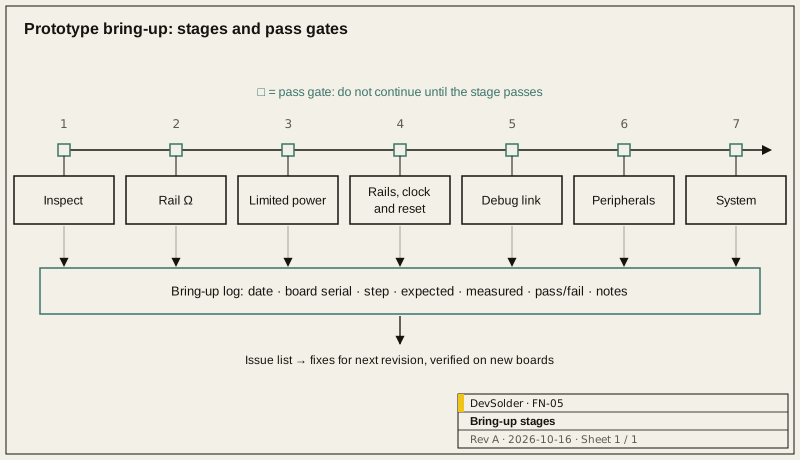
Before you start: bench safety
Bring-up involves new hardware that may not behave as designed. Before starting, confirm the voltages present on the board and treat any mains-connected or high-voltage section as a separate activity with its own procedure, isolation and qualified people. Use eye protection when powering a board for the first time, keep batteries and supercapacitors disconnected until their charging circuits are verified, and keep the bench clear of anything that could short exposed nets. The procedure below assumes low-voltage boards; adapt it before use on anything else.
1.0 Before the boards arrive
Prepare these while the boards are still at the assembler.
| Item | Purpose |
|---|---|
| Bring-up plan | The stages below, adapted to this board, with expected values for each rail and current |
| Expected current per stage | So an abnormal draw is recognised immediately |
| Test firmware | Minimal images that blink a pin, print over UART, and exercise one peripheral each |
| Schematic and layout at the board’s revision | Annotated with test point locations |
| Equipment list | Bench supply with current limit, multimeter, oscilloscope, debug probe, logic analyser, thermal camera or probe if available |
| Bring-up log template | One row per check: date, board serial, step, expected, measured, pass/fail, notes |
Size the order by role: one board stays unpowered as a reference, one is reserved for destructive tests and rework, and every engineer working in parallel gets a unit.
2.0 Stage 1: inspection
- Check against the assembly drawing: orientation of polarised parts, pin 1 of ICs, connectors, any DNF parts.
- Look for solder bridges on fine-pitch parts and for tombstoned passives. Leadless packages may need X-ray to confirm joints; ask the assembler whether they ran it.
- Confirm board revision and serial marking, and record them in the log.
3.0 Stage 2: unpowered checks
Measure resistance from each power rail to ground, with the board unpowered. A near-zero reading points to a short, a reversed part, or a bridge. Compare against your reference board and against expected values from the design. Check the main input for reverse-polarity protection behaviour if the design includes it.
4.0 Stage 3: first power
Use a bench supply with the current limit taken from the expected draw for this stage in the bring-up plan, with the margin written next to it. If the supply goes into limit, stop. If the design allows, power one rail or subsystem at a time using the isolation links planned in the layout.
- Bring the supply up slowly where practical, watching the current.
- If current hits the limit, remove power and investigate. Do not raise the limit to see what happens.
- Feel or image for hot parts in the first seconds.
- Record the current at each step.
5.0 Stage 4: rails, clocks and reset
| Check | How |
|---|---|
| Rail voltages | Meter at test points, compared to tolerance in the design notes |
| Rail ripple and noise | Oscilloscope with short ground connection at the point of load |
| Power sequencing | Multi-channel capture of rails and enables at power-on |
| Reset | Reset line released after rails settle; supervisor thresholds as designed |
| Clocks | Oscillator starts within the datasheet start-up time and runs at the expected frequency; the PLL locks before reset release |
Problems found here, such as a rail that sequences in the wrong order, explain symptoms that would otherwise be chased as firmware faults later.
6.0 Stage 5: debug link
Connect the debug probe and confirm you can read the processor’s ID, halt it, and write and read RAM. Then program the smallest test image and confirm it runs: a pin toggle, then a UART message. If the debug link fails, check the interface pins, the reset line and the boot-mode pins before suspecting the processor.
7.0 Stage 6: peripherals one at a time
Bring up each interface with dedicated test firmware, in an order that respects dependencies (for example, external memory before anything that needs it).
- Communication buses (I2C, SPI, UART): confirm each device responds, with a logic analyser capture saved in the log.
- External memory: full read/write pattern test, not a single address.
- Radios: confirm the module responds and can be configured; RF performance testing is a separate activity with the right equipment.
- Analog inputs: measure known reference inputs and compare.
- Power modes: measure current in each sleep mode, because leakage paths are a common first-revision finding.
- USB and other external interfaces: enumeration on the host OSes you support.
When something fails, change one thing at a time, and write down what you changed, including bodge wires and component swaps. If a bodge wire made it work, log the wire (from, to, why), or the next revision ships with the same fault.
8.0 Stage 7: system test
Run the integrated firmware through the main use cases, then edge cases: low battery, brown-out, hot plug, long running. At this point the production test plan can be drafted from what was measured, because you now know which checks catch real faults.
9.0 The bring-up log and issue list
The log records what was measured, on which board, under which conditions. From it we derive an issue list with a severity and proposed fix per item:
| Field | Example content |
|---|---|
| ID | BU-007 |
| Board / serial | Rev A, unit 3 |
| Symptom | What was observed |
| Root cause | Confirmed, or suspected with evidence |
| Workaround on this revision | Rework or firmware setting |
| Fix for next revision | Schematic or layout change |
| Status | Open, fixed in design, verified on new revision |
The issue list becomes the change list for the next revision. Each item should be verified on the next boards, not closed when the design file changes.
10.0 Who does what
We can run bring-up on boards from a DevSolder design package or on boards designed by your team. We work alongside your engineers, either at the bench or remotely while they run the plan, with one shared log. The Assembly, Bring-up and Test page explains the options; firmware for bring-up is covered on Embedded Firmware, and the path from first prototype onward is on Prototype to Production. Start with Discuss a Project.
Frequently asked questions
How many prototype boards should we order?
Count it from roles: one board stays unpowered as a reference, one is reserved for destructive tests and rework, and each engineer working in parallel on firmware or test gets a unit. Board cost decides how much spare you add on top.
Should firmware be ready before bring-up?
Small test images should be ready: one per stage, each doing one thing. The full application is not needed and can get in the way, because a failure in it is harder to trace back to hardware.
What happens if we find a design error?
It goes into the log and the issue list with a workaround for the current boards, such as a rework or a firmware setting, and a fix for the next revision. Work continues on the reworked boards while the design change is made.
Can bring-up be done remotely?
Parts of it can, with someone at the bench following the written plan and a shared log, and a remote engineer watching captures and the debug session. First power and anything involving rework go faster with an experienced engineer at the board.