Hardware Design Package Deliverables List
The files a build-ready hardware design package should contain, how each is checked, and how one revision tag keeps every party on the same board.
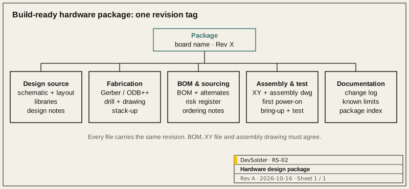
Direct answer. A build-ready hardware design package contains editable design sources, fabrication outputs, a BOM with checked alternates, placement data, assembly notes, first power-on checks, bring-up and test procedures, any firmware needed for test, a change log and known limits. All files carry the same revision. Use this list to check a package before you order boards.
1.0 What “build-ready” means
A package is build-ready when an engineer who was not part of the design reviews can order parts, have boards fabricated and assembled, power them up safely and test them, using only the files. That is the test we apply. If a step needs a phone call to the designer, a document is missing.
The list below is the structure DevSolder uses for a Build-Ready Hardware Package. Use the same list to audit a package from another supplier.
2.0 Design sources
| Deliverable | Contents | Check |
|---|---|---|
| Schematic source | Native CAD project files | Opens in the stated tool version; matches the PDF |
| PCB layout source | Native CAD layout files, with design rules | Opens without errors; design rule check passes with documented exceptions |
| Libraries | Symbols and footprints used, or the project-local library | Footprints match BOM part packages |
| Schematic PDF | Full schematic, readable, with revision in title block | Same revision as sources |
| Design notes | Key decisions: power architecture, interface choices, protection, layout constraints | Explains the non-obvious parts |
Editable sources are what make later revisions possible without reverse-engineering. Ownership and licensing of the sources are agreed before work starts and differ between a custom design and a licensed reference design.
3.0 Fabrication outputs
| Deliverable | Contents | Check |
|---|---|---|
| Fabrication data | Gerber X2, ODB++ or IPC-2581 | Layer set matches stack-up; generated from tagged revision |
| Drill data | Plated and non-plated drill files with drill map | Format and units stated |
| Fabrication drawing | Board outline and dimensions, stack-up, impedance requirements, finish, tolerances, special notes | Revision matches fabrication data |
| Panel drawing | If panelised by the designer: rails, fiducials, tooling holes, break method | Agreed with the assembler |
4.0 BOM and sourcing
| Deliverable | Contents | Check |
|---|---|---|
| BOM | Reference designators, quantity, description, manufacturer, manufacturer part number | Every placed reference appears once; DNF parts marked |
| Approved alternates | Alternates checked against the parameters that matter in the circuit | Status per alternate: approved or candidate |
| BOM risk register | Lifecycle, sources, availability notes with check dates | Dated; high risks have a mitigation |
| Special parts | Drawings or specs for cables, labels, custom mechanical parts | Each has a revision |
| Ordering notes | Minimum order quantities, moisture-sensitive parts, parts that need programming before assembly | Visible to whoever orders |
5.0 Assembly and test
| Deliverable | Contents | Check |
|---|---|---|
| Placement (centroid) file | Reference, X, Y, rotation, side | Rotation convention stated; spot-checked |
| Assembly drawing | Top and bottom placement, polarity marks, DNF parts, special instructions | Matches BOM and placement file |
| Assembly notes | Steps that are easy to get wrong: hand-soldered parts, conformal coating keep-outs, connectors fitted after test | Short and specific |
| First power-on checklist | Resistance checks on rails, current limits, what to look for in the first seconds | Expected values listed |
| Bring-up procedure | Stage-by-stage checks with expected readings and test point locations | Each step has a pass criterion |
| Production test procedure | What an operator measures or runs, and what passes | Operator can run it without the designer |
| Test fixture notes | Test point list, coordinates, required signals | If a fixture is planned |
6.0 Firmware and calibration
Where the board needs firmware or calibration to be tested:
| Deliverable | Contents |
|---|---|
| Test firmware | Images and source for bring-up and production test |
| Programming procedure | Tool, interface, steps, and how to verify the programmed image |
| Calibration procedure | Equipment, steps, limits, where results are stored |
Product application firmware is separate work, described on the Embedded Firmware page.
7.0 Documentation and revision control
| Deliverable | Contents |
|---|---|
| Revision tag | One identifier shared by every file in the package |
| Change log | What changed in each revision and why |
| Known limits | Open issues, untested conditions, items deferred to a later revision |
| Certification notes | Target standards discussed, design choices made for them, items left for the test lab |
| Package index | List of files with their purpose |
7.1 Folder structure
A predictable folder layout makes a package easy to check. One structure we use:
| Folder | Contents |
|---|---|
| 00_index | Package index, change log, known limits |
| 01_design_source | Native schematic and layout projects, libraries |
| 02_fabrication | Fabrication data, drill files, fabrication drawing, panel drawing |
| 03_assembly | BOM, alternates, placement file, assembly drawing, assembly notes |
| 04_test | First power-on checklist, bring-up procedure, production test procedure, fixture notes |
| 05_firmware | Test firmware images and source, programming and calibration procedures |
| 06_reference | Schematic PDF, design notes, datasheets referenced in the design, certification notes |
Each archive is named with the board name and revision, and a checksum list for the files is included so recipients can confirm nothing was changed or lost in transfer. When a new revision is released, the previous package is kept unchanged; boards already built from it remain traceable to the exact files used.
8.0 How to use this list
When receiving a package, check each row: does the file exist, does it carry the right revision, and does it agree with the files around it. Mismatches between BOM, placement file and assembly drawing are the most common problem in practice, and the cheapest to find before ordering.
You can build from the package yourselves, or ask DevSolder to source parts and arrange fabrication, assembly and test with an itemised quote. See Hardware Design Package, BOM, Alternates and Procurement Risk, Assembly, Bring-up and Test and Sourcing and Manufacturing. Request a package through Discuss a Project.
Frequently asked questions
Is Gerber alone enough to build a board?
Gerber files describe the bare board. To get assembled boards you also need the BOM, placement file and assembly drawing, and to test them you need the bring-up and test procedures. A package without those works only if the designer is available to answer questions.
Why include editable source files?
Every product goes through revisions. With the native schematic and layout files, your team or another supplier can make the next change directly. Without them, the next revision starts with redrawing the design.
What is the difference between approved and candidate alternates?
An approved alternate has been compared on the parameters that matter in this circuit and fits the footprint, preferably with boards built using it. A candidate looks suitable but has not been checked to that level yet.
Does the package include certification?
The package records the target standards and the design decisions made for them. Certification testing itself is done by an accredited lab you choose, and the results may lead to changes in a later revision.
How do we check a package we received from another supplier?
Go through the tables above row by row. For each file, confirm it exists, opens, carries the package revision and agrees with its neighbours: BOM against placement file and assembly drawing, fabrication data against the stack-up in the drawing. Then try the first power-on checklist on paper against the schematic. Gaps found this way are cheap to close before boards are ordered, and DevSolder can run the same check as a review if you prefer an outside view.